Telescopic Hydraulic Cylinder: How 3-Stage Staging Works
News Details
What Is a Telescopic Hydraulic Cylinder?
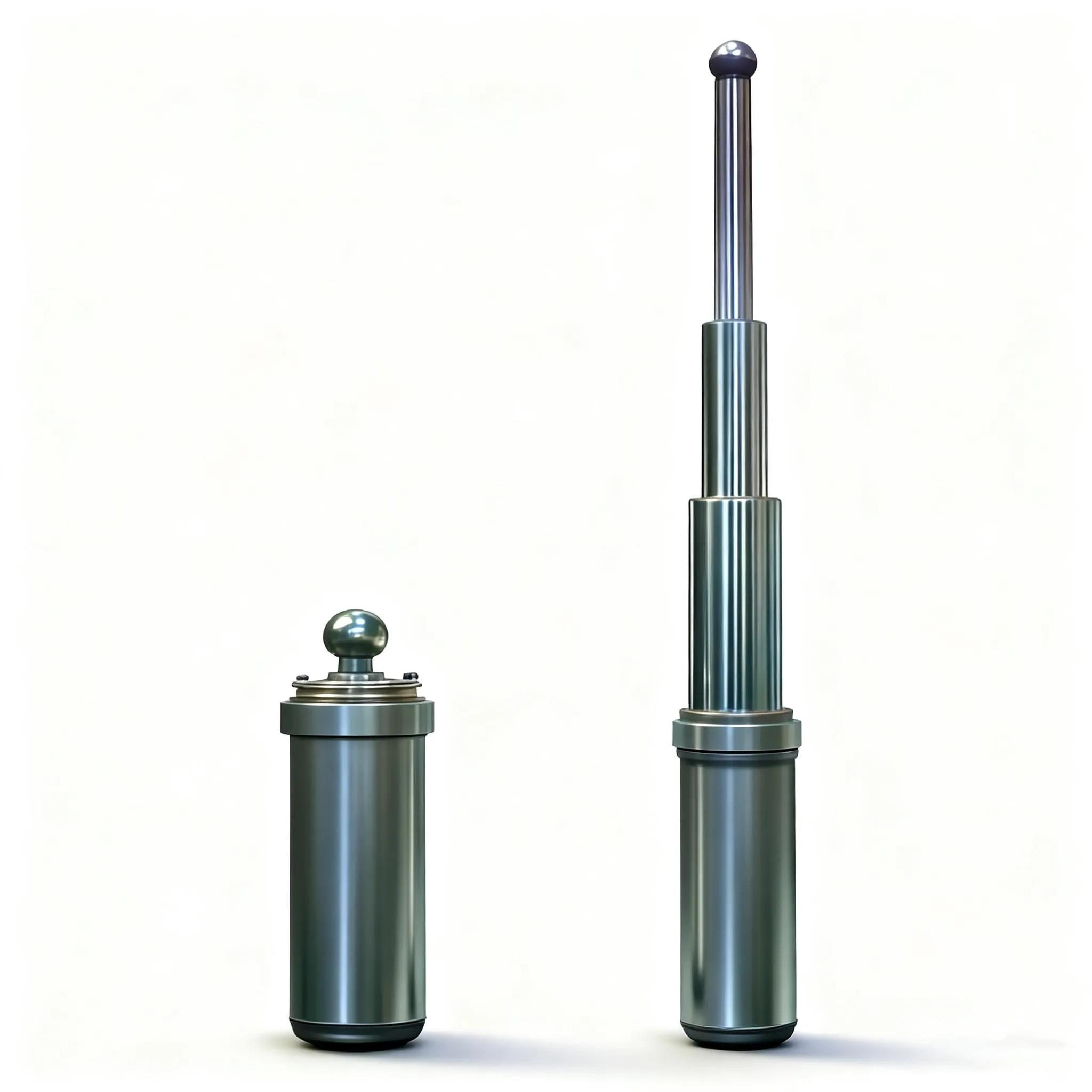
A telescopic hydraulic cylinder is a multi-stage actuator built from two to five concentric tubes that slide inside one another, so a long working stroke fits into a short retracted package. There is no single piston rod: each tube is a stage, and each stage acts as the barrel for the one inside it.
The nesting is the point. A dump trailer needing 1,300 mm (51 in) of lift may have 500 mm (20 in) under the bed, where a single-stage cylinder would need a rod longer than its stroke. A three-stage unit collapses to roughly one third of its extended length at the same pressure. The cost is structural: every stage is a thin-walled tube, so the load path is longer and guiding more delicate.
- Outer barrel — base stage, ported, carrying the mount.
- Intermediate sleeves — honed internally, each a barrel in turn.
- Final plunger — smallest stage, solid or thick-walled.
- Gland and guide set — locates each sleeve, houses wiper and seal.
How Does a Telescopic Cylinder Extend in Stages?
Extension is strictly sequential: the largest stage moves first, and each later stage starts only after the previous one hits its stop. No control valve produces this sequence — effective area does.
Oil entering the base port acts on the full area of the first stage. Largest area means highest force and, for a given flow, lowest speed. When that stage bottoms on its stop ring, the same pressure acts on the annulus of the second stage: smaller area, less force, more speed. The pattern repeats until the smallest stage is out.
- Oil enters the base port and fills the volume under the largest stage.
- Stage 1 extends with the whole nested stack ahead of it; nothing else moves.
- Stage 1 reaches its stop ring and pressure transfers to the next annulus.
- Stage 2 extends faster and with less force, carrying the remaining stages.
- Final stage tops out. Total stroke is the sum of each stage's travel, less guidance overlap.
Retraction reverses it: the load pushes the stages home, smallest first, and oil returns through the same port. That is why a single-acting unit must be mounted rod-up — without gravity it has no return force.
Why Force Falls and Speed Rises as Stages Extend
Force equals pressure times effective area; speed equals flow divided by that same area. As stages extend, area shrinks, so force drops and speed climbs, always in inverse proportion.
That is not a flaw to engineer away — it is what makes the product useful. A loaded dump body is heaviest at breakaway, when the load is compacted and the geometry gives least mechanical advantage, and that is precisely when stage 1 delivers peak force. Past about 30° of tilt gravity assists, and the small fast stages finish the dump.
| Stage | Effective area | Relative force | Relative speed | Load condition |
|---|---|---|---|---|
| 1 (largest) | Largest | 1.00 | 1.00 | Breakaway, full load |
| 2 | −36% | 0.64 | 1.56 | Load partly lifted |
| 3 | −59% | 0.41 | 2.44 | Approaching full angle |
| 4 (smallest) | −74% | 0.26 | 3.81 | Topping out, little resistance |
Two consequences follow. Never size on total force alone: check the load still moves with the smallest stage carrying it. And if high force is needed at the end of travel, specify single-stage or plunger instead.
Single-Acting or Double-Acting: Which Design Fits?
Single-acting units extend hydraulically and retract under load or gravity, using one port. Double-acting units add a second port and a retract circuit, so they can pull the stages home against resistance.
Gravity decides it. Any vertical application with weight above the cylinder — dump bodies, tipper trailers, hatch covers — suits single-acting: simpler, cheaper, fewer seals. Horizontal axes, or motion where retraction does real work, need double-acting.
| Criterion | Single-acting | Double-acting | Choose double-acting when |
|---|---|---|---|
| Ports | One | Two | Retraction must be powered |
| Retract force | Load or gravity | Full hydraulic | The load will not return itself |
| Orientation | Rod up, near vertical | Any | The axis is horizontal or inverted |
| Seal complexity | Lower | Higher | Downtime cost exceeds seal cost |
| Best fit | Tippers, trailers, compactors | Pushers, lift platforms, marine | Position must hold under load |
A third option for horizontal duty is a single-acting unit with an external return spring or counterweight. It moves complexity from the circuit into the machine structure, so it is a machine-level decision.
Need a multi-stage cylinder sized to your lift geometry? Send your closed length, stroke, load and mounting orientation. Our engineers return a stage layout, a force curve and a quotation within 24 hours.
What Seals and Guides Keep the Stages from Leaking?
Every stage interface carries a rod seal, a wiper and a wear ring, and that triple determines service life more than any other factor. A three-stage cylinder has three such interfaces, at the same pressure but different sliding conditions.
Each element has one job. The rod seal, usually polyurethane for extrusion resistance, holds the pressure boundary. The wear ring, commonly PTFE-filled or phenolic, carries side load and keeps the sleeve concentric so the seal is never pinched. The wiper scrapes grit off the incoming surface before it reaches the seal lip — in quarry duty this part does more for longevity than the seal itself.
Surface finish is the other half. Bores are honed to roughly 0.2–0.4 µm Ra; exposed sleeves are hard chrome plated to 20–30 µm at 800–1,000 HV. Too rough abrades the seal, too smooth cannot hold an oil film. One detail is often missed in procurement: intermediate sleeves must be honed inside to barrel standard, because that is what they are. A supplier who hones only the outer barrel ships a cylinder that weeps at stage two.
What Causes Telescopic Cylinder Failure in the Field?
Most failures trace to four causes: contaminated oil, side loading, seal extrusion from overpressure, and impact damage to an exposed sleeve. All four are predictable, and three are preventable with maintenance rather than redesign.
- Contaminated oil — particles migrate to the tightest clearance, the stage seal, scoring seal and sleeve. A 10 µm return filter and scheduled oil changes remove most of the risk.
- Side loading — an extended stack is a long cantilever; lateral force from a misaligned pivot multiplies through the stages and appears as wear-ring failure and chrome spalling.
- Overpressure — a relief valve set above the seal's extrusion limit deforms the lip at the gland gap. It does not fail at once; it deforms, weeps, then fails.
- Impact damage — the smallest stage lives outside the barrel, so one stone strike opens a corrosion pit no wiper can clean.
Symptoms usually name the cause. Drift under hold means internal bypass at whichever stage carries the load; a pause at a stage transition points to a bent sleeve or worn guide; creeping extension with the valve closed indicates a leaking check valve upstream.
Where Are Telescopic Cylinders Used?
Telescopic cylinders appear wherever a long straight stroke must fit a package too short to contain it. The design is chosen for geometry first, force second.
The largest application is tipping: dump trucks, tipper trailers and waste transfer trailers lift a body through 45–60° with the cylinder under the floor. A three-stage unit with a closed length under 600 mm (24 in) delivers a stroke that would otherwise need a cylinder twice as long as the chassis allows. Other uses include scissor and boom lifts, where staging reaches height without a mast; ship hatch covers, driven by a horizontal double-acting unit; waste compactors, where a long push stroke must fit a fixed frame; and clamping fixtures, where a short closed height simplifies the machine envelope.
How Do You Specify a Telescopic Cylinder?
Start from machine geometry and the load curve, then let those determine stage count — never the reverse. A supplier given a stage count before the load curve quotes something that works on paper and stalls in the field.
Six data points decide the design; no accurate quotation is possible without all of them:
- Closed length available in the mounting envelope, in mm.
- Stroke at the load point, and whether geometric or cylinder stroke is quoted.
- Load curve — force at breakaway, mid-lift and full extension, with moment arm at each position.
- Operating pressure, and whether an upstream relief valve protects the seals.
- Mounting orientation and type: vertical single-acting, horizontal double-acting, or angled pivot.
- Duty cycle: cycles per day, oil cleanliness target, dominant wear mechanism.
Three commercial points are worth settling too. Ask for the stage diameter list, not just the bore, because final-stage force limits the application. Ask which standard the mount follows, ISO 6020/2 or a customer drawing. And confirm what the pressure test covers: a unit proof-tested only at the base stage has not been tested at the stage that leaks.
Frequently Asked Questions
How many stages can a telescopic cylinder have?
Most production units use two to five stages. Three is the common compromise for tipping duty, balancing stroke against force loss on the final stage. Beyond five, the sleeves become too thin to guide reliably and a different lifting mechanism is the better answer.
Why does my telescopic cylinder extend slowly at first?
Because the first stage has the largest effective area, so a given pump flow moves it slowest. Speed rises as each smaller stage takes over. If the whole cycle feels slow rather than just the start, check pump flow and the relief setting.
Can a telescopic cylinder be mounted horizontally?
Only if it is double-acting. A single-acting unit relies on gravity or load weight to retract the stages, and neither exists on a horizontal axis. Installed horizontally, the stages stay extended, the seals sit exposed to dirt, and the cylinder cannot return under its own power.
What is the difference between stroke and closed length?
Stroke is total travel of the final stage from retracted to extended, equal to the sum of each stage's travel. Closed length is the retracted overall length. The ratio between them, typically 2.5:1 to 4:1, is the packaging benefit you are buying.
How often should the seals be replaced?
Replace on condition rather than on a calendar. Inspect the wiper and exposed chrome every {{service-interval}} and replace the seal stack when drift exceeds the limit or weeping appears at a gland. Halve that interval in quarry or marine duty.
Can a damaged stage be repaired instead of replaced?
Often yes. A scored sleeve can be re-chromed and re-honed if wall thickness allows, and glands can be re-sealed individually. A bent sleeve or cracked stop ring is a replacement, because straightening destroys the guidance tolerance the seal depends on.


