How to Specify a Custom Hydraulic Cylinder: Bore, Stroke, Pressure and Mounting
News Details
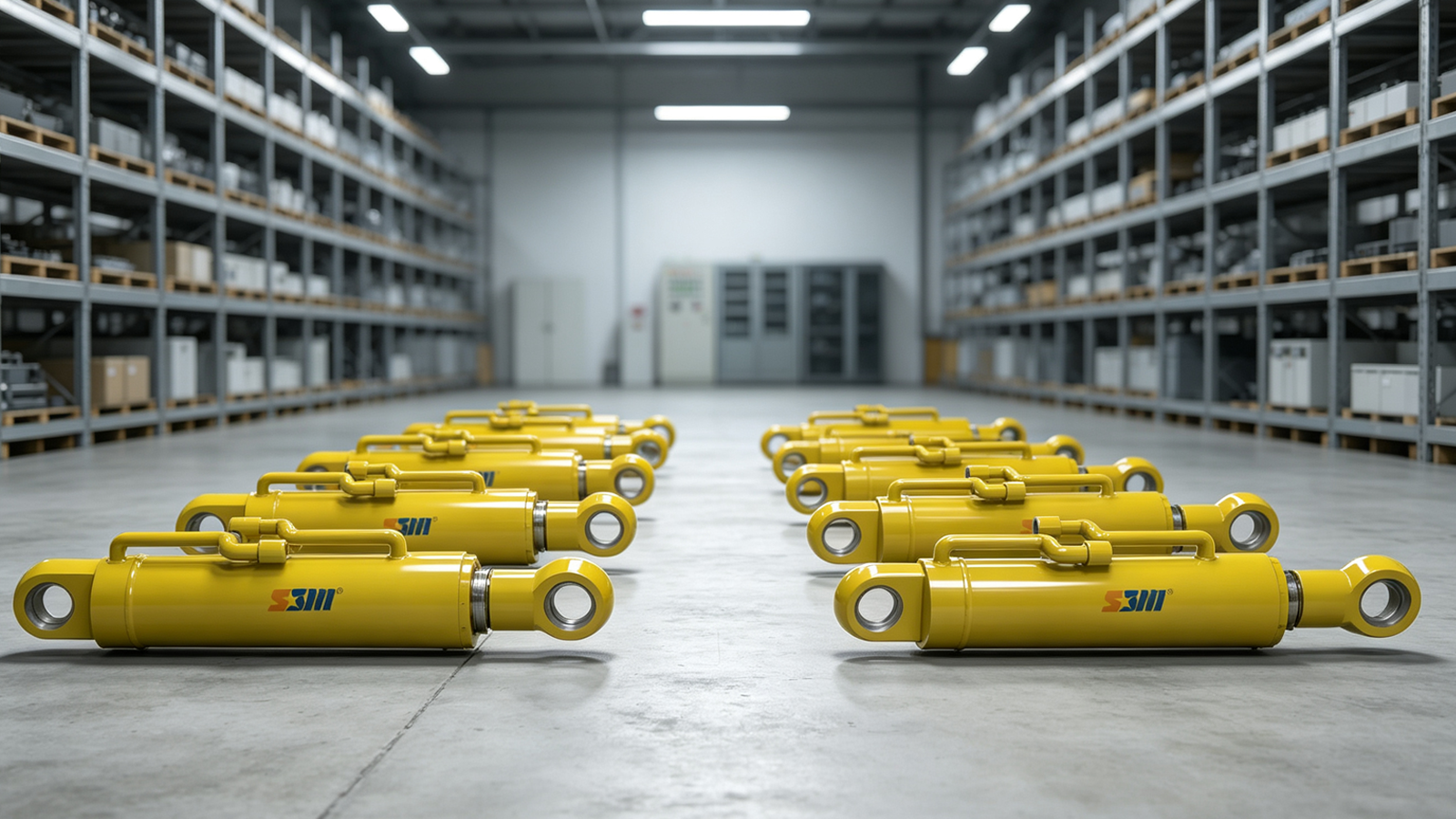
A custom hydraulic cylinder must do more than fit into a machine. It must produce enough force, move through the full working range, handle pressure peaks, and stay aligned under load. If one part of the specification is wrong, the cylinder may leak, bend, wear too fast, or fail to move the load.
Therefore, a clear specification is the first step toward a reliable cylinder. It also helps the custom hydraulic cylinder manufacturer select the right barrel, piston rod, seals, ports, and mounting parts.
This guide explains the main points you need to define before ordering a custom or OEM hydraulic cylinder.
Start with the Application
Before choosing the bore or stroke, describe what the cylinder must do. A supplier needs to understand the machine, not just the cylinder dimensions.
Start with these questions:
· What will the cylinder lift, push, pull, clamp, tilt, or steer?
· What is the normal load?
· What is the highest possible load?
· Will the load change during movement?
· How fast should the cylinder extend and retract?
· How many cycles will it complete each hour?
· Will it face shock, vibration, dust, salt, water, or high heat?
· Is the cylinder used indoors or outdoors?
· How much space is available when the cylinder is open and closed?
For example, a cylinder used on a hydraulic press has different needs from one used on a mobile crane. The press may need a rigid flange mount and slow, controlled force. In contrast, a crane may need a pivot mount that follows the movement of the boom.
A clear application description allows the manufacturer to build a hydraulic cylinder design around real working conditions.
Calculate the Required Cylinder Bore
The cylinder bore is the inside diameter of the barrel. It controls the piston area and, as a result, the force the cylinder can produce.
The basic formula is:
Force = Pressure × Piston Area
For extension force, use the full piston area. For retraction force, subtract the piston rod area because the rod takes up part of the working area.
However, the theoretical force is not the same as the force available at the machine. Friction, pressure loss, seal drag, and changing load angles can reduce the final output. Therefore, include a suitable design margin.
As a simple example, suppose a machine needs 100 kN of push force and the working pressure is 20 MPa. The theoretical piston area is:
100,000 N ÷ 20,000,000 Pa = 0.005 m²
This equals a bore of about 80 mm. Yet an 80 mm bore leaves little room for pressure loss or added load. Therefore, the final design may use a larger standard bore after the manufacturer checks the full system.
A heavy duty hydraulic cylinder often needs a wider safety margin because it may face impact loads, uneven ground, or sudden pressure changes.
When specifying the bore, provide:
· Required extension force
· Required retraction force
· Normal working pressure
· Maximum system pressure
· Expected pressure loss
· Desired safety margin
Do not choose a bore based only on the pump’s rated pressure. Instead, use the pressure that reaches the cylinder during normal work.
Define the Correct Stroke Length
Stroke is the distance the piston rod moves from the fully closed position to the fully open position. It should cover the full working travel without forcing the cylinder against its internal end stops.
First, measure the required movement at the cylinder mounting points. Do not use the travel of the bucket, platform, blade, or machine arm as the cylinder stroke. Linkages can change the travel ratio.
Next, check both installation dimensions:
· Retracted length, often called closed length
· Extended length, often called open length
Space becomes more important when specifying a long stroke hydraulic cylinder. As stroke increases, the piston rod becomes more likely to bend or buckle under a push load. Long cylinders may also need more guide support.
Possible solutions include:
· A larger piston rod diameter
· A stop tube to increase bearing distance
· Stronger rod and barrel materials
· A different mounting position
· External guides for the moving load
· A telescopic design when closed space is limited
The cylinder should move the load, but it should not act as the machine’s main guide rail. External guides should control side movement whenever possible.
Select Working and Test Pressure
Working pressure is the pressure the cylinder handles during normal use. Maximum pressure is the highest short-term pressure that may occur. Test pressure is used during inspection to confirm the strength and sealing of the finished cylinder.
These values should not be treated as the same number.
For each project, provide:
· Normal working pressure
· Peak pressure
· Hydraulic relief valve setting
· Expected pressure spikes
· Required test pressure
· Cycle rate and duty time
Pressure peaks may occur when a load stops quickly, a valve closes, or a machine hits an obstacle. Although these peaks may last only a short time, they can damage seals, ports, welds, and cylinder mounts.
Shellppon’s SB-Y1 cylinder range, for example, supports working pressures from 16 to 25 MPa with custom bore, stroke, and mounting options. For higher loads, Shellppon has also supplied 35 MPa cylinders for a major port lifting project.
The right pressure rating must cover both steady work and short-term shock. Therefore, discuss the full hydraulic circuit with the manufacturer instead of giving only the pump pressure.
Size the Piston Rod for Load and Stability
The piston rod transfers force from the piston to the machine. Its diameter affects retraction force, strength, buckling resistance, and seal life.
A rod under tension is mainly limited by material strength. However, a rod under compression may buckle before the material reaches its full strength. This risk increases with:
· Longer stroke
· Smaller rod diameter
· Higher push force
· Pivot mounting
· Poor alignment
· Side load
· Long distance between support points
For this reason, a long stroke hydraulic cylinder often needs a larger rod than a short cylinder with the same bore and pressure.
The rod surface also matters. Hard chrome plating is widely used because it provides a smooth, wear-resistant surface for the rod seal. However, marine, mining, and chemical applications may need added corrosion protection or stainless steel.
Ask the manufacturer to check rod buckling, bearing load, surface finish, hardness, and corrosion resistance as part of the hydraulic cylinder design.
Choose the Right Mounting Style
Cylinder mounting controls how force passes into the machine frame. The wrong mount can create side load, bend the rod, or place stress on the cylinder barrel.
Common mounting options include:
· Flange mounting: Suitable for presses and fixed machines with straight axial loads.
· Foot mounting: Provides rigid support for industrial equipment and hydraulic power units.
· Clevis mounting: Allows the cylinder to pivot as the machine linkage moves.
· Trunnion mounting: Supports heavy pivoting loads around a fixed point.
· Center pin mounting: Allows movement around the middle of the cylinder body.
· Spherical bearing mounting: Helps handle small changes in alignment.
Pivot mounts work well for cranes, loaders, mining machines, and other moving linkages. However, the pins must remain parallel, and the cylinder must be free to follow the load path.
Fixed mounts work best when the load moves in a straight line. Even then, the frame must be stiff enough to keep the rod and barrel aligned.
Shellppon offers base and head trunnion mounts, foot mounts, center pin mounts, and round flange mounts for different OEM hydraulic cylinder applications. This range allows the mounting system to match the machine instead of forcing the machine to fit a standard cylinder.
Specify Ports, Speed, and Cushioning
The cylinder bore and rod do not control speed by themselves. Speed depends on oil flow, piston area, port size, hose size, and valve capacity.
If the ports are too small, they can cause heat, pressure loss, noise, and slow movement. Therefore, provide the required extension and retraction speed along with the available flow rate.
Also consider cushioning. A cylinder that stops a heavy load at full speed may create a strong pressure spike. Internal cushions can slow the piston near the end of its stroke. External valves can also control deceleration.
Your specification should state:
· Port thread and size
· Port position
· Required movement speed
· Available oil flow
· Need for end cushioning
· Need for load-holding or counterbalance valves
· Need for position or pressure sensors
For mobile equipment, compact port placement may be just as important as flow capacity. The ports must remain clear of the frame, hoses, and moving parts throughout the full stroke.
Match Se


