Hydraulic Rotary Cylinders for Oilfield Valves: Working Principle, Selection, and Design Limits
News Details
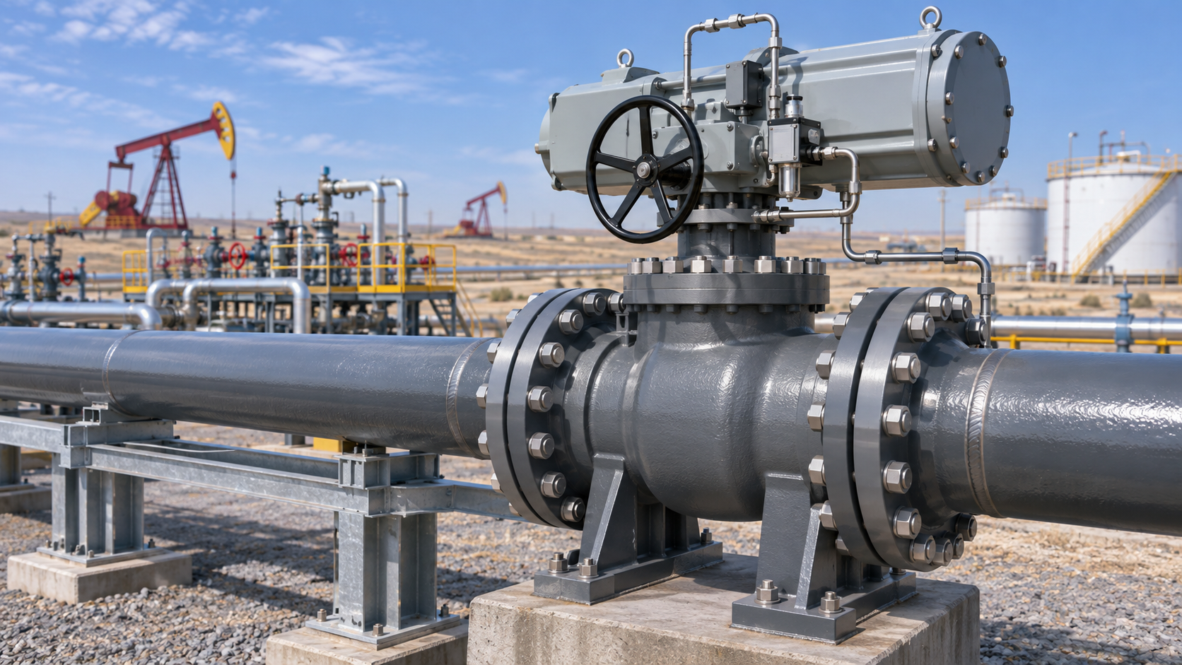
Oilfield valves must operate under pressure, vibration, and harsh weather. At the same time, drilling equipment and offshore platforms often leave little room for an actuator.
A hydraulic rotary cylinder converts fluid pressure into controlled turning motion. For quarter-turn ball, butterfly, and plug valves, it can provide the 90° movement needed to open or close the flow path.
Helical rotary actuators are worth considering where installation space is tight. However, reliable valve operation depends on the complete assembly: actuator, coupling, controls, hydraulic supply, and emergency operating system.
Contents
- What is an oilfield hydraulic rotary cylinder?
- How does a helical rotary actuator work?
- How do rotary actuator designs compare?
- How should valve torque be checked?
- How much oil and flow are required?
- What makes an actuator suitable for oilfield service?
- What are the main design limits?
- What information is needed for a custom solution?
What Is an Oilfield Hydraulic Rotary Cylinder?
A hydraulic rotary cylinder is a limited-angle actuator that turns an output shaft or flange. Connected to a valve stem through a suitable coupling, it provides the torque needed to move the valve between its operating positions.
Typical applications include quarter-turn valves on process lines, manifolds, and selected drilling systems.
However, not every oilfield valve uses rotary motion. Many gate valves and surface safety valves require linear actuators. Therefore, the valve type and stem movement must be confirmed before choosing an actuator.
How Does a Helical Rotary Actuator Work?
A helical rotary actuator uses an internal mechanism to convert piston travel into rotation.
In a typical sliding-spline design:
- Hydraulic oil enters a pressure chamber.
- Pressure moves the piston along the actuator body.
- Helical splines guide the moving parts and turn the output shaft.
- The shaft transfers torque through the coupling to the valve stem.
- Reversing the pressure supply reverses the movement.
This arrangement places the motion conversion inside a compact housing. Other helical designs use different internal mechanisms, so output characteristics must be checked against the selected model.
Helical vs. Rack-and-Pinion vs. Vane Actuators
Each design offers benefits. The best choice depends on the valve duty rather than a single performance claim.
| Design | Main benefit | Key selection check |
| Helical | Compact layout with enclosed motion conversion | Torque, backlash, efficiency, and service access |
| Rack-and-pinion | Direct drive with established valve-control layouts | Installation envelope, tooth loading, and clearances |
| Vane | Simple rotary mechanism with few moving parts | Seal leakage, pressure rating, and available travel |
Helical actuators can suit confined installations, as demonstrated by commercial quarter-turn valve actuator designs. Nevertheless, they are not automatically the best option for every oilfield valve.
Published torque and positioning figures belong to specific products. They should not be treated as general ratings for all helical cylinders.
How Do You Select the Required Torque?
Start with the valve manufacturer’s torque data under the actual service conditions.
Check:
- Breakaway torque: The torque needed to start movement after the valve has remained still.
- Running torque: The torque required during travel.
- Seating and unseating torque: The torque needed near the closed position.
- Service effects: Differential pressure, temperature, deposits, corrosion, and time between operations.
Then compare the valve’s torque requirement with the actuator’s available output throughout the stroke, using the minimum available hydraulic pressure.
Apply the margin agreed with the valve supplier and project specification. Also check the valve stem’s maximum allowable torque. An oversized actuator can damage the stem, seats, or coupling if pressure is not properly limited.
Extra torque should not replace inspection of a seized or damaged valve.
How Much Oil and Flow Does the Actuator Need?
For an initial estimate:
Operating time in seconds ≈ 60 × stroke volume in litres ÷ flow in litres per minute
For example, an actuator requiring 0.5 litres for a 90° stroke would take about 6 seconds at 5 litres per minute.
This is an ideal estimate. Actual time depends on valve restrictions, load, oil temperature, leakage, and available pressure.
Opening and closing times may also differ. For that reason, specify both directions separately and confirm performance through testing.
Why Consider Hydraulic Actuation for Oilfield Valves?
Hydraulic actuation can provide substantial torque within a compact installation. It also allows the power unit to be placed away from the valve, with hoses or tubing carrying pressure to the actuator.
With suitable controls, the system can support:
- Remote valve operation.
- Controlled opening and closing speeds.
- Position feedback.
- Emergency movement using stored energy.
- Integration with an electro-hydraulic control package.
However, hydraulic pressure alone does not guarantee stable positioning, shock resistance, or safe shutdown. Those functions depend on the circuit and mechanical design.
Position Holding and Fail-Safe Movement Are Different
A valve may need to remain in place after power loss, close automatically, or open automatically. The required action comes from the process safety assessment.
Position holding may use pilot-operated check valves or another suitable holding arrangement. Leakage, temperature changes, and trapped pressure still need consideration.
Fail-safe movement requires a reliable energy source and control path. Depending on the design, this may involve a return spring or a hydraulic accumulator.
An accumulator must be sized for the required stroke, minimum operating pressure, temperature range, and reserve capacity. Its ability to complete an emergency action must be verified.
Commercial fail-safe systems use spring-return or accumulator arrangements to move valves to a defined safe position.
What Protection Does the Oilfield Environment Require?
Outdoor and offshore service can expose actuators to salt spray, dust, vibration, and large temperature changes.
Material, coating, fastener, and seal choices should match these conditions. Seal selection must also account for the hydraulic fluid and operating temperature.
Hazardous-area suitability requires a review of the complete package, including solenoids, switches, sensors, and potential ignition sources. Good sealing alone does not establish explosion protection.
Likewise, an actuator suitable for deck installation is not automatically suitable for subsea use. Subsea service requires checks for external pressure, pressure compensation, connectors, and any ROV override interface.
Where Can the System Perform Poorly?
Performance can fall short when the actuator is selected only by nominal torque.
Common problems include insufficient supply pressure, excessive return pressure, poor coupling alignment, contaminated oil, and unsuitable seals.
Other limits require particular attention:
- Vibration: Hydraulic damping does not by itself prevent unwanted valve movement.
- Travel accuracy: Accurate shaft positioning does not prove that the valve seals correctly.
- Fast closure: Actuator cushioning reduces mechanical impact, but pipeline surge requires a separate process review.
- Emergency operation: A holding valve cannot provide the energy needed to complete a shutdown stroke.
Closure time should therefore be set from both the shutdown requirement and the pipeline’s transient behavior.
What Should You Provide for a Custom Actuator Review?
For a useful technical discussion, provide:
- Valve type, size, pressure class, and process conditions.
- Torque requirements across the operating stroke.
- Maximum allowable stem torque.
- Required travel and opening/closing times.
- Minimum and maximum hydraulic pressure.
- Mounting drawings, coupling dimensions, and space limits.
- Temperature, corrosion, vibration, and hazardous-area requirements.
- Required response to power or hydraulic supply loss.
- Feedback, override, inspection, and testing requirements.
Discuss Your Oilfield Valve Project with Shellppon
A compact helical actuator can be a strong candidate for quarter-turn oilfield valves. The final choice should follow verified torque data, installation limits, and a clearly defined emergency response.
Shellppon Hydraulic provides hydraulic cylinder manufacturing and OEM/ODM services. To discuss component selection or a custom project, contact Shellppon with your valve data, drawings, and operating requirements.


